Getting Started
Choosing to build your own piece of gear is a rewarding and great learning experience. If it’s your first time, this guide will walk you through the steps to complete your Elements build. If you’re a grizzly old pro, you’re probably not even reading this!
Patience
Do you want to have a failed build and a huge headache? Rushing through the build and paying little attention to the instructions will result you in being sloppy with your soldering and assembly. As much as you want that cool new piece of gear up and running NOW, take your time and make sure to take breaks. Move through each step carefully, take pride in your build. A sloppy build, even if it's working, won’t give you the same sense of satisfaction as that of a good, clean, and neat build. Patience is key to the success of your build.
Tools
You’ll need a few basic tools to complete this build. Though this list may not be exhaustive, it’ll give you an idea of what you should have on hand.
- Soldering Iron It goes without saying that you need a soldering iron, get a decent one. At the very least you should have a 25-watt pencil-style soldering iron. Weller sells the WP-25 for about $40 USD and it’s a solid entry level soldering iron. Radio Shack sells a 40-watt model for about $10 USD. I’ve not used that model, but I bet it’s better than a lighter. If you’re going to build a few units and do some repairs, consider getting an adjustable temperature solder station. The Hakko 936 is a tried and tested unit that sells for about $70 USD. It’s a fabulous tool.
- Soldering Tip Most decent irons will allow you to insert different tip styles. For most PCB work, including this build, you’ll want a small chisel tip. I use the Hakko 936 iron with a D18-D16 tip. This is a 1.6mm radius chisel tip.
- Solder Solder is kind of like guitar strings in that you really need to feel which one is right for you. I went through a few types before I found one I liked. There are a few different considerations such as lead or lead-free, no-clean type, and the diameter. I use Kester #245 no clean solder. It's a 0.031” diameter 63/37 alloy. It needs no flux cleaning and is available at many local and online retailers (Part #24-6337-8800).
- Digital Multi-Meter (DMM) A good DMM is as important as a soldering iron. An auto-ranging DMM will make sorting resistors a breeze and help avoid time consuming errors. Testing and troubleshooting will make having a good DMM a must. An inexpensive model is better than nothing, but a good model will be a trusted tool on your bench and in your studio for years. It’s important to note that cheap meters generally do not measure AC (audio) level accurately above a few hundred Hertz at best. In audio we like to deal with 1KHz test signals, so get a nice meter. Fluke is the standard for DMMs. A Fluke 177 is another tried and tested workhorse. It’s not cheap, but it’s not that expensive for something you will use and depend on every day.
- Panavise Do you need a Panavise? No! Will it make your PCB stuffing much easier and make you look cool? Yes! These are not that expensive. Consider getting one.
- Pliers, Cutters, and Strippers A pair of fine needle nose pliers will come in handy for some of the final assembly work. I bet you already have a pair of these! Small diagonal cutters are a must. You’ll need these for trimming the component leads. Having a decent pair of wire strippers in the 16-26 AWG range is something you should have.
- Hex Key Set Also known as a Hex Wrench, Allen Wrench, and Allen Key. Whatever you call it, you need one to install the knobs. Consider getting a set with a nice storage case.
- Nut Drivers These are not as fun as they sound. These are used to tighten various nuts in assembly, including the faceplate components. Due to the length of the potentiometer and t-pad shafts, you’ll need a nut driver with a fairly deep channel. I used to use pliers to tighten these. I’d mare the nuts, scratch the panel and drop a few F-bombs. Do yourself a favor and get a Nut Driver set. I picked up a 7 piece set at a hardware mega-store for about $15.
Soldering Guide
Soldering WELL is one of those things that seems easy until you try it. Once you try, it starts to seem kind of difficult. Then finally you figure it out and it seems easy again.
Rather than trying to explain it to you, I went online, to find the best video tutorial I could. I settled on Dave Jones’ tutorial on the EEVBlog. Dave’s a wacky cat, but so are most guys who inhale lead all day. The tutorial is presented in three parts: tools; soldering through-hole components; and soldering surface mount components. For our purposes, I recommend you watch part 1 and 2. The videos are lengthy at about 25 minutes each, but they are well worth watching. Even I learned a few things.
The videos can be seen by visiting:
hairballaudio.com/eevblog-solder-tutorials
PCB Overview
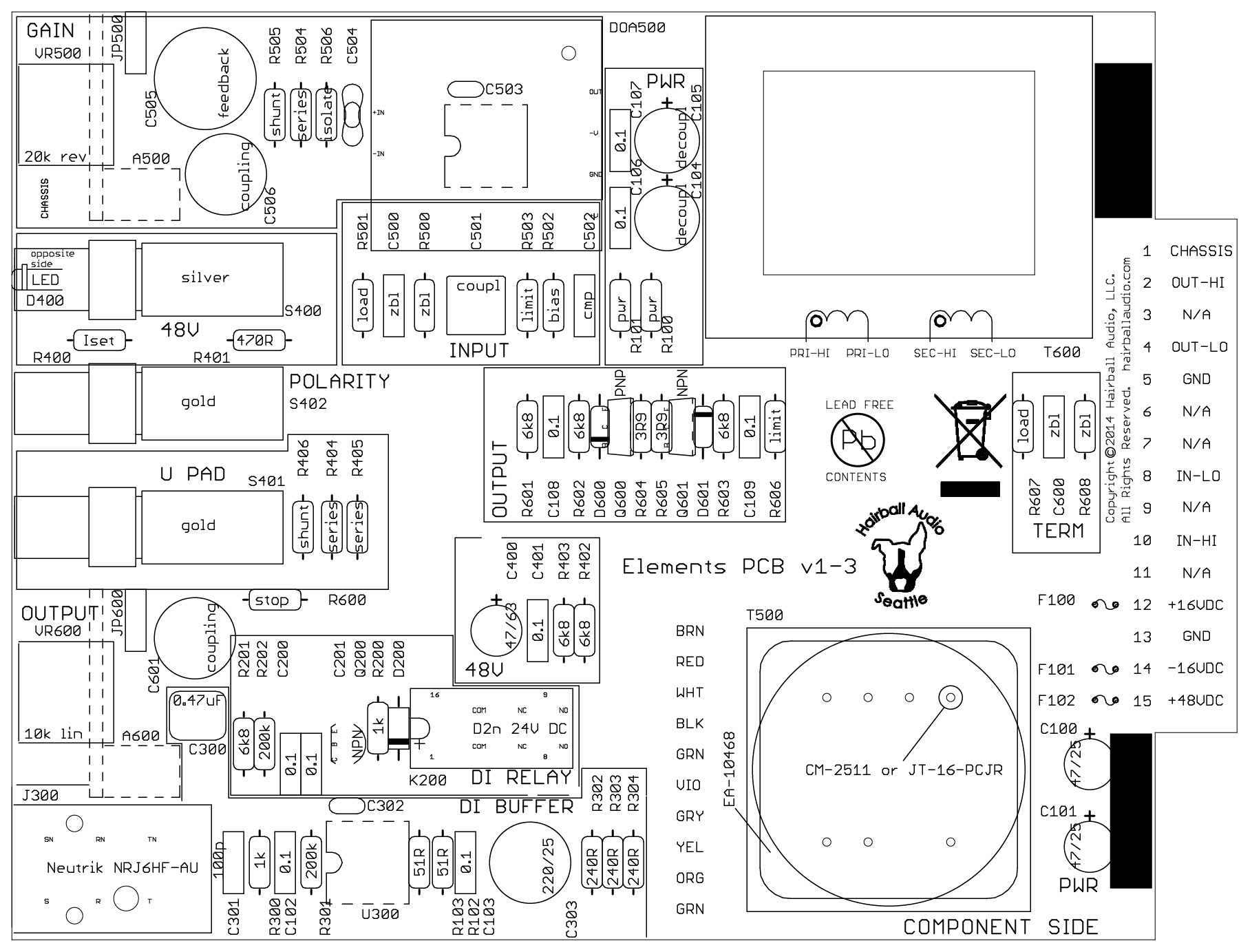
The PCB is laid out in blocks. Component values follow these designations:
100 = Power Supply Distribution and Decoupling ("PWR")
200 = Direct Input Relay ("DI RELAY")
300 = Direct Input Buffer Amplifier ("DI BUFFER")
400 = Preamp Input Circuitry ("48V", "POLARITY", "PAD")
500 = Input Amplification Stage ("INPUT", "GAIN")
600 = Output Amplification Stage ("OUTPUT", "TERM")
A = Assembly
C = Capacitor (assorted)
D = Diode (rectifier, signal, or Light Emitting)
DOA = Discrete Op Amp
F = Fuse (PTC resettable)
H = Hardware
J = Jack (connector)
JP = Jumper
K = Relay
Q = Transistor
R = Resistor
S = Switch
U = Integrated Circuit
VR = Variable Resistor (potentiometer)
Populating the Printed Circuit Board (PCB)
Build Maps
Click the appropriate link below to access the BOM and build map for your kit.
PDF Bill of Materials
You should also reference the PDF BOM below. It includes a little more detail about some components that may be trickier to identify.
Note: When reading the BOM, R is ohms and K is kilo-ohms and they are placed where the decimal would be. Example:
39R = 39Ω 3R9 = 3.9Ω 15K = 15K Ω 1K5 = 1.5KΩ
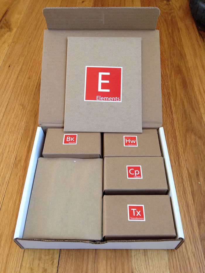
All the parts listed in your BOM will be included in your kit. The kits includes the following boxes:
Base Kit: Includes all common components required in the circuit regardless of which preamp you're building.
Elements Specific: This box is labeled either Gold, Copper, or Bronze. It includes the components used for your particular build. They are used in addition to the base kit. You'll want to combine your base kit and specific kit as you start to stuff your PCB.
Hardware: Box includes all of the front panel parts and screws.
Transformers: Box contains the input and output transformers for you build.
In addition to the BOM and components, you'll want to grab your soldering iron, solder, digital multimeter (DMM), lead trimmers, and a lead forming tool or needle-nose pliers. The lead forming tool shown below is Mouser part 5166-801, but a pair a needle-nose pliers will work just as well.
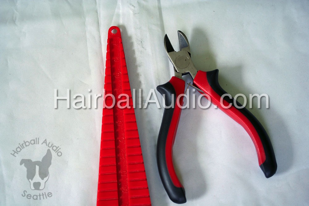 Lead forming tool and angle cutters shown above.
Short and Omits
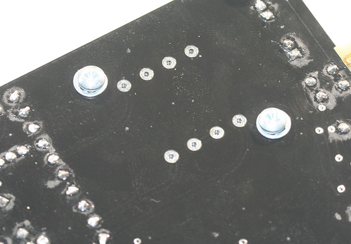
First things first! You may notice that your BOM may list "Short" or "Omit" for a particular part. Short means the designated component must be shorted by directly connecting its pads. You can easily do this with a cut resistor leg.
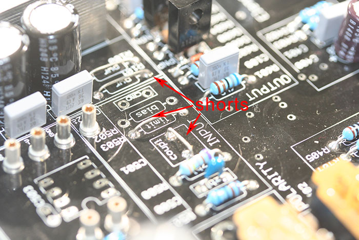 Shorts on a gold PCB shown above. Your build may or may not have these shorts, refer to the BOM.
Once you begin stuffing the PCB you will have lots of cut component leads to make any shorts. Go ahead and solder in the shorts as you cut off component legs.
Omit means that you should simply leave that component empty. Do not apply a short or any other component. Leave it empty!
Op-Amp Sockets
Let’s get started!
Again, as you stuff the PCB, use the components from the base kit and Elements specific kit to stuff your PCB. Personally, I like to begin by inserting the op-amp sockets. They are located in the base kit box.
You should have 6 op-amp sockets. The sockets must be inserted from the top side (silkscreen side) of the PCB. There are a few different ways to solder the op-amp sockets. You can solder from the top, bottom, or both. The most important part is that you get good solder flow around the entire socket and PCB pad connection. I like to tilt my PanaVise so it’s parallel to my table surface with the silkscreen side up. Place the sockets in the socket pads. The hollow end should be facing up, this hollow shaft accepts the op-amp pins. Working from the topside, place your solder tip so it makes contact with the socket and pad, just like you would with any other component.
 Top soldering op-amp pins shown above. Be patient, let it heat and go easy on the solder. Be sure not to apply too much pressure to the socket or it may lift causing it to sit slanted on the board. The socket is a large part that will need about 5 seconds of heating time to get good flow. Applying a touch of solder to the solder tip, PCB, and socket connection point should allow for good heat transfer. When you start to see that solder flow, apply some solder to the opposite side of the pad while keeping your iron tip in the original location. This should give you a good flow around the pad. Remember less is more when it comes to solder. Too much solder can wick up into the socket making it impossible to insert the op-amp later. If you have a good connection on the top side there is no need to solder the bottom side. Once you have all the sockets soldered, you can wiggle them to confirm you have a good electrical and mechanical connection.
Resistors
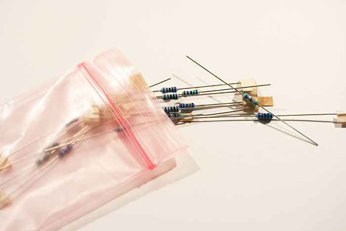
Make sure you use both the basic kit and your element kit specific components. Components are generally stuffed from shortest to tallest for easiest assembly. Let's start with resistors since they are small and account for many of the on-board components.
Take your time, soldering resistors is easy, but misplacing a 270Ω for a 270KΩ resistor is not an easy thing to sort out when your build doesn’t work right. Test each resistor with your DMM Ω setting before soldering it in place. You'll rest easy later on.

Shown above, a 150KΩ is confirmed. I know my resistor color band codes, but I’ve checked this 150KΩ resistor anyway. Not only have I double-checked my eyes, I’ve confirmed it’s working correctly.
Resistors are not polarized. You can insert them in either direction. Take your time (really, please TAKE YOUR TIME), the extra time now can save you hours or days of troubleshooting.

ATTENTION BRONZE BUILDERS!!!
R503 is a 68K resistor that has a 100pF ceramic disc capacitor in parallel with it. Both the cap and resistor are inserted into R503. For Bronze, C503 is left empty.
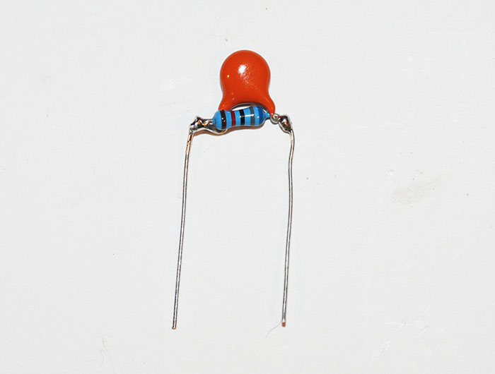
The cap is also not polarized and can be inserted either way. Start by bending the resistor and wrapping the cap leads around its legs. Be careful not to bend the leads too close to the cap body as it can be damaged.
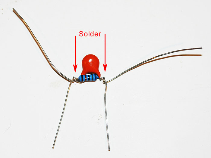
Add just enough solder to bond them and then cut the cap leads. You'll be left with a part you can easily insert into R503. This might be your first time doing this so it may not look pretty or sit flush. That's ok as long as the solder joints are good.
Now that you have a bunch cut resistor leads, go ahead and solder in those shorts!
Diodes
Diodes are next. They are bent and soldered like resistors, however, there is one major difference: DIODES ARE POLARIZED DEVICES. Components that are polarized have a positive and negative lead which must be inserted into the correct pads on the PCB. These leads are the Anode (+) and Cathode (-).
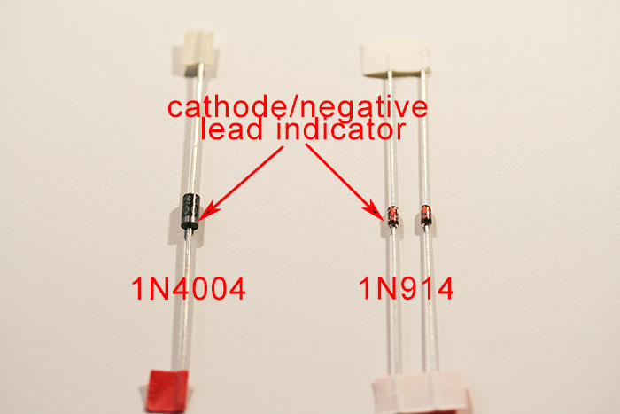
There are 3 diodes used in the Elements series and they are part of the base kit used in all revisions. There are two 1N914 diodes used in the output stage, and one 1N4001 used to protect the relay coil. Your diode will have its name (1N4004 or 1N914) printed on the diode itself. Look really close!
On your diode you will notice one lead is marked with a line. This line identifies the negative or cathode lead. The silkscreen also shows the diode with a line at one side. This indicates how the diode should be inserted. Pretty easy!
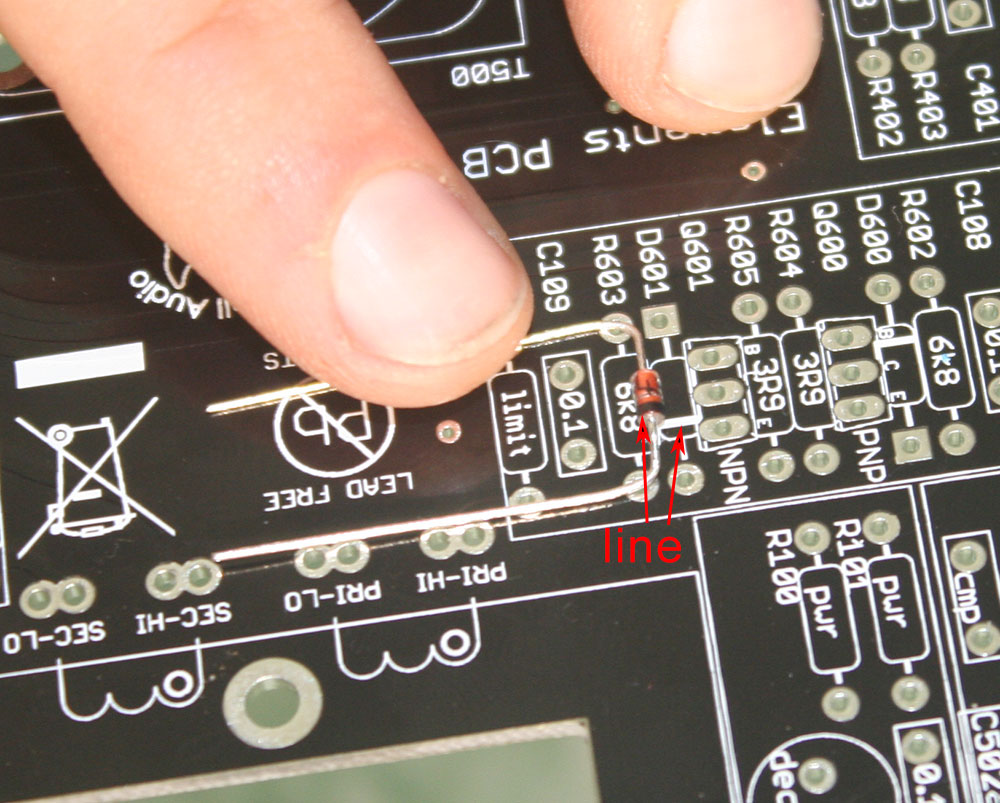 Proper diode alignment is shown above.
Transistors
We could go a few different directions at this point, but let's move to transistors. There are three, and though two look the same, they're not!

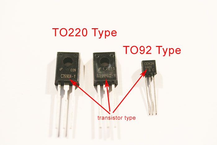
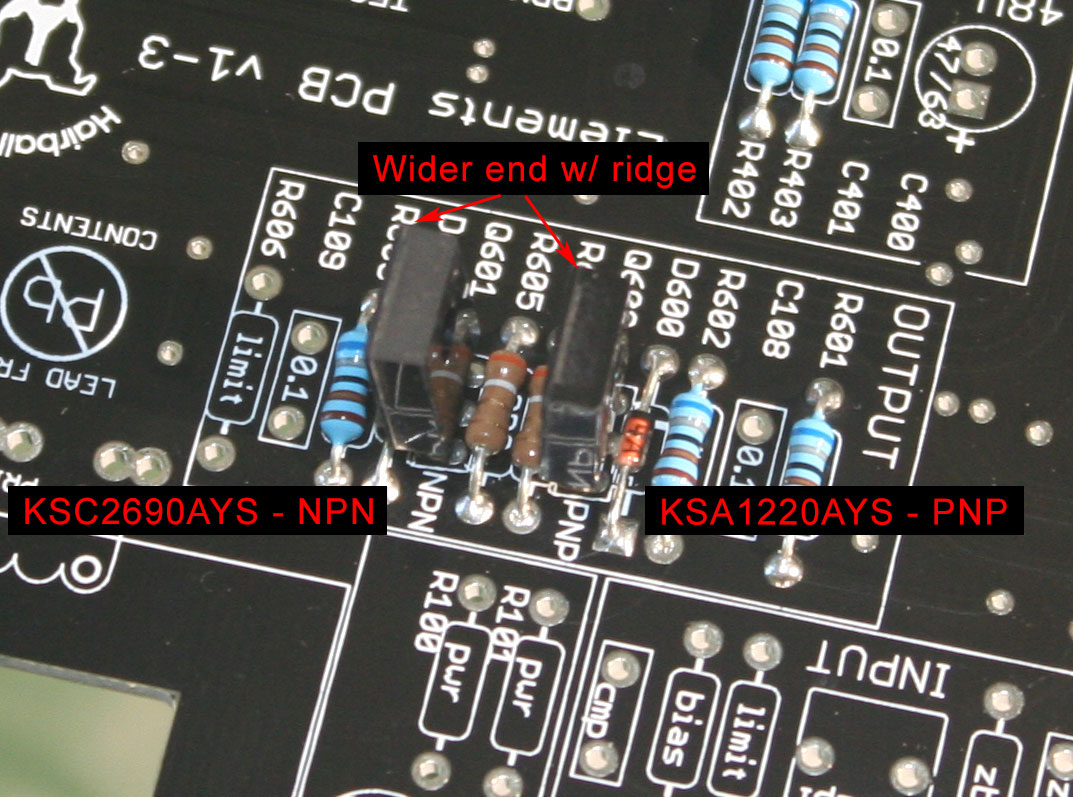
There are two large rectangular TO-220 package transistors. KSA1220AYS (Q600) is a PNP transistor and KSC2690AYS (Q601) is an NPN. Look close! They're labeled. These are bipolar junction transistors (BJTs) and they have a collector, an emitter, and a base. These can vary from component to component. To make it easy for you, the PCB silk-screen matches the package of the transistors. For these TO-220 transistors, you'll notice the silkscreen has a trapezoidal shape with a line on the wider end. If you look at the top of the transistor, you'll notice its slight trapezoidal shape, which is subtle, however more obvious is the ridge on the wider end. Place the component in the PCB so the ridge and line match up. Also, make sure you insert the PNP and NPN in their proper places.
The last transistor is a TO-92 package which is D shaped and it controls the DI relay. It's also a BJT transistor and inserting it correctly is as easy as lining up the D shaped transistor with the D shape on the silkscreen.
Capacitors
Let’s talk capacitors!
The images that follow cover the types found in Elements; your build may or may not have all these types.
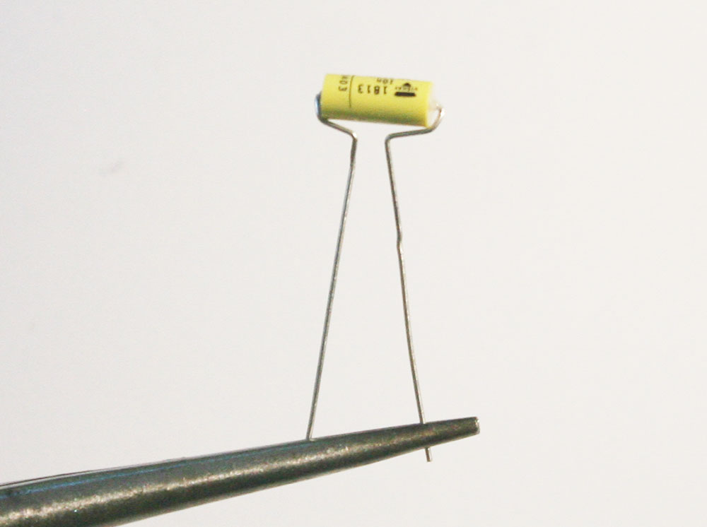
Capacitors have two lead style: axial and radial. Radial caps have two leads on the bottom of the cap. Axial lead capacitors have leads coming from either side of the cap.
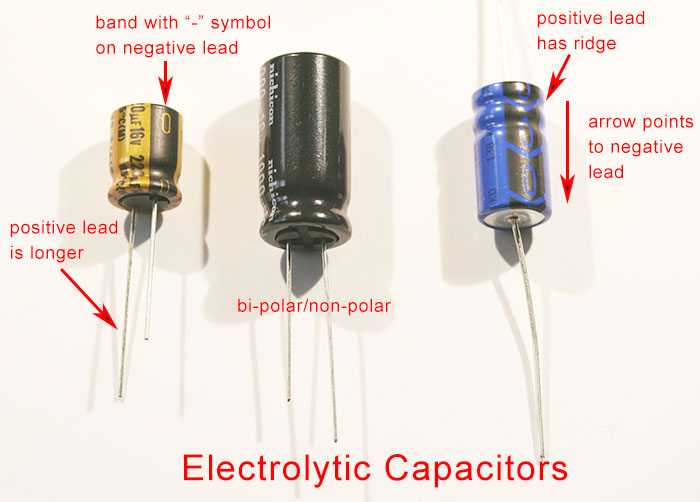 Electrolytic capacitor types found in the Elements series shown above. Most of the electrolytic and tantalum caps we'll be using are polarized. Meaning they must have a positive (+) and negative (-) lead that must be installed correctly. The negative lead is marked with a "-" and an arrow pointing to the lead. In radial caps the positive lead is longer and in axial caps the positive is at the end with the ridge. The Base and Gold kits have a few Nichicon VP series capacitors which are bi-polar/non-polar and can be inserted in either direction. However, for the sake of consistency and muscle memory, you should use the longer lead as positive.
On the PCB the positive pad is always square.
Axial electrolytic capacitors need to be inserted vertically on the elements PCB. Start by identifying the negative lead and the negative PCB pad. Determine whether curling the negative lead or positive lead will make the cap fit best with the components around. Bend that lead 180 degrees.
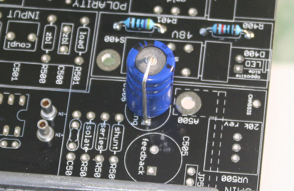
In the case shown above the positive lead is curved over. You can see the top has ridges and the pad is square this indicates that they are both positives. Now solder the lead into place confirming the leads are inserted into the proper pads. Also, confirm the lead that is curled over is not touching the metal face of the opposing side of the cap. This would create a short and take the cap out of the circuit.
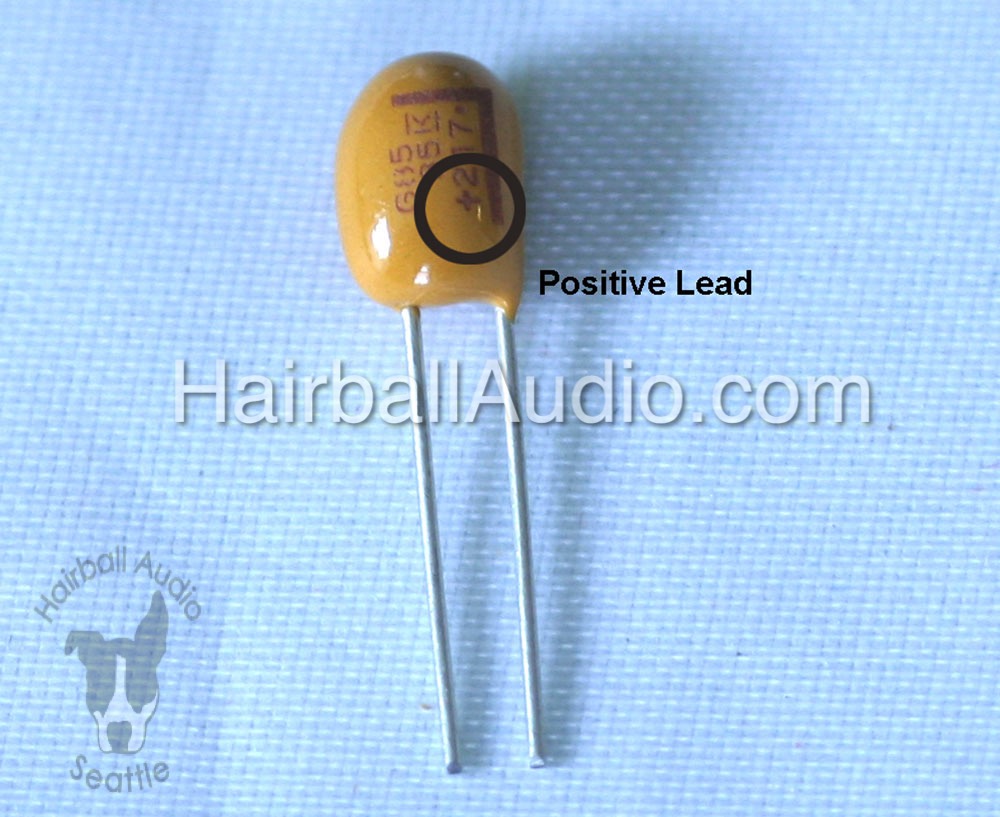
Tantalum caps (copper only) are polarized as well. Their positive lead is marked with a "+" and a line pointing to it.
COPPER NOTE: C501 is tantalum and polarized however, the pads on the PCB do not indicate polarity. In this case, the pad closest to the rear edge card connector is positive and the pad closest to the front panel is negative.
The film and ceramic capacitors are non-polarized and can be inserted in either direction. Some kits have axial lead film caps. To make them fit you may need to bend the leads inward slightly. It’s pretty straight forward.
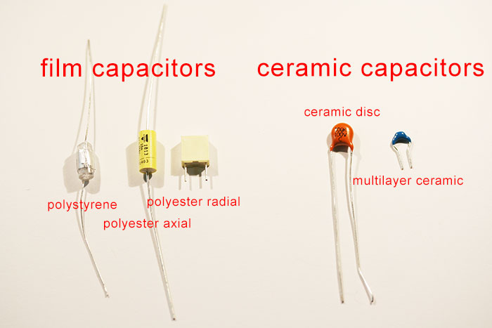
Film capacitor types found in the Elements series shown above.
Axial lead film cap with leads bent. These are NOT polarized.
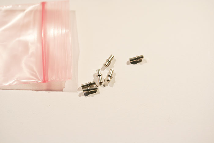
Fuses
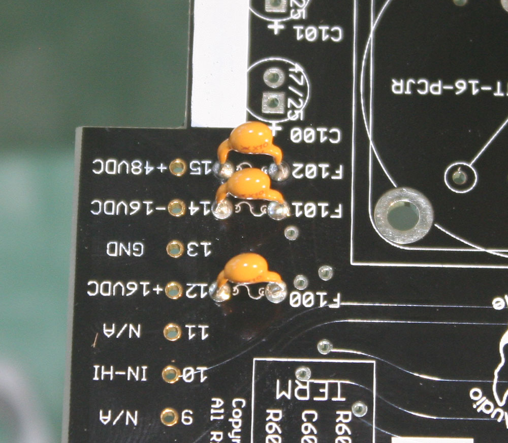
The base kit includes 3 identical fuses.
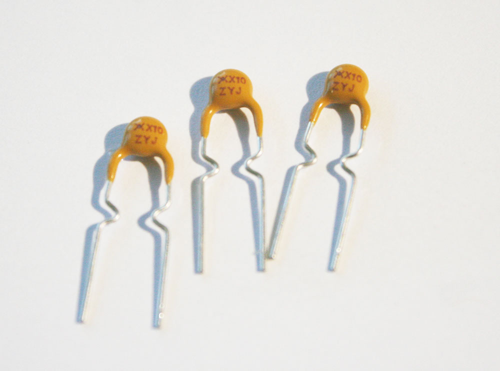
These protect the +16 VDC, -16VDC, and +48VDC rail from exceeding 100mA which should never happen in a properly functioning Elements mic pre. These little awesome dudes will protect your build, rack, and other modules from catastrophe. What's very cool is that when they trip, all you need to do to reset them is power cycle your rack.
These are not polarized and all three are identical. You'll need to pinch and wiggle them a little to get them in. It's a little sexy. They are hard to make look pretty, so just get them in and soldered well. They ain't for looking at, they're for saving your gear!
LED
There is still one diode we need to insert. It's the Light Emitting Diode (LED). It indicates when phantom power is activated. It slowly dims when deactivated to let you know when the phantom cap is fully discharged.
It MUST be inserted before the switches.
It is also polarized. The long lead is positive and the flat side of the LED ridge is aligned with the negative lead. On the PCB the positive pad is square.
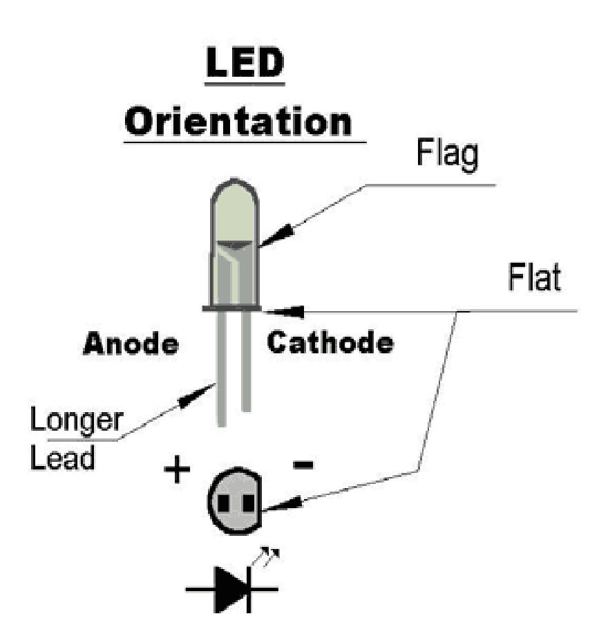
The LED is mounted on the BOTTOM of the PCB. You'll need to bend the LED leads at a 90-degree angle for mounting. Start by inserting the LED leads into the proper holes (it's polarized!) and stop at the point where you think bending it forward will cause the ridge to extend just past the edge of the PCB. This should be just below the bump-out on the leads.
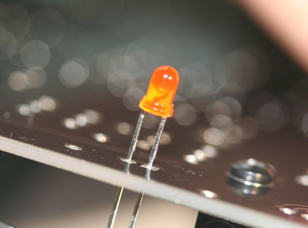
Inserted LED ready for bending. Now push the LED forward.
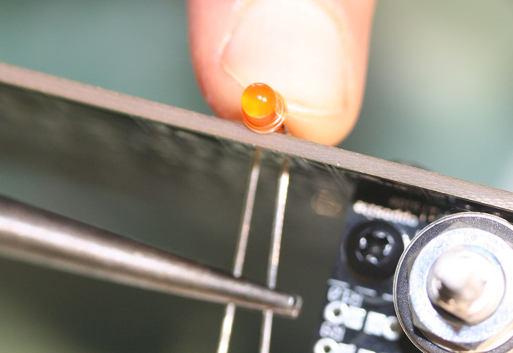
The LED bottom ridge is just over the edge and ready for soldering and trimming. The bottom is flush to the PCB edge.
Relay
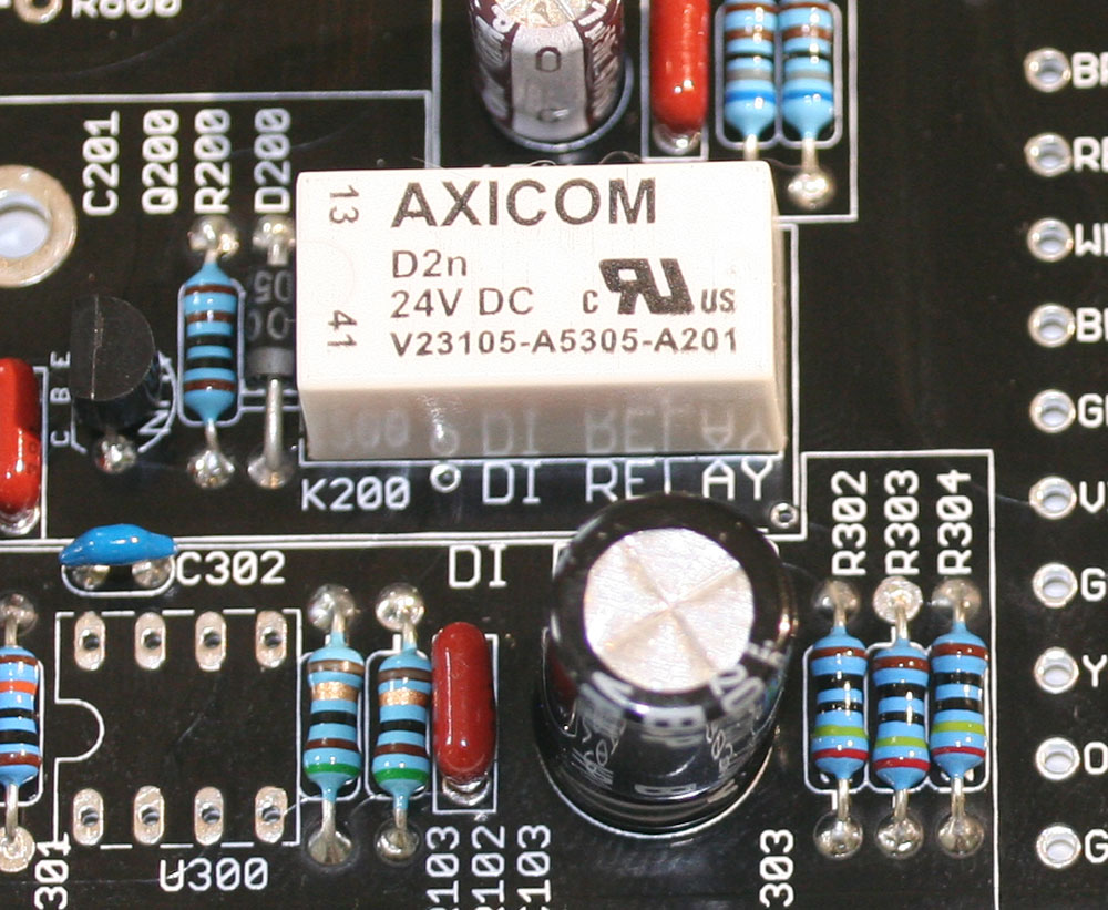
The Axicom 24V relay controls whether your pre is using the XLR mic input on the rear of the rack or the 1/4 inch unbalanced instrument DI input. By default it's set to the XLR mic input. However, when you insert an unbalanced 1/4" cable into the DI jack the relay switches the input to the DI input.
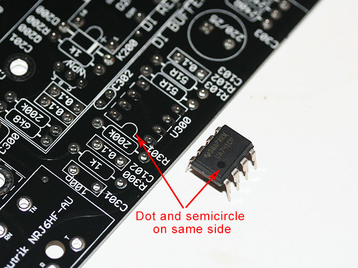
It needs to be inserted correctly. If you look at the silkscreen you'll see that the end of the relay closest to the front panel has semi-circle. The relay has this same semi-circle, simply line them up!
Dip-8 IC
The kit includes an integrated circuit (IC) that has 8 leads, 4 on either side. It must be installed correctly and in the correct location. There are two DIP-8 footprints on the PCB. DO NOT install the IC in U500 which sits under the discrete op-amp. This footprint is for silver builders who wish to use an DIP-8 IC rather than a discrete op-amp. The IC in your kit is used as a DI buffer and is installed in U300.
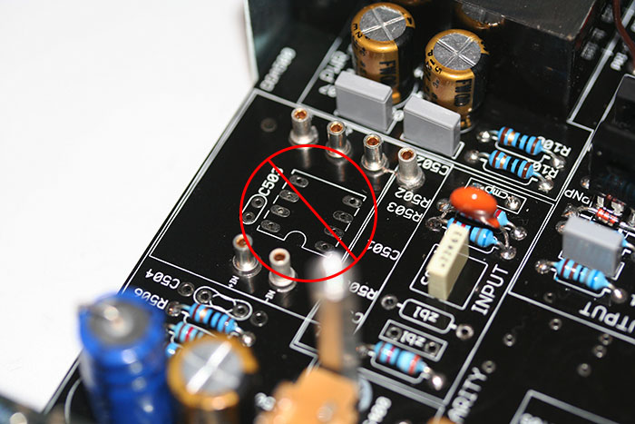
The footprint for U300 has a semicircle on one end. Your IC will either have the same semicircle or a dot. Insert the IC so the semicircles align or the dot is on the same side as the semicircle.
You'll have to pinch the leads a little to insert it.
Switches
There are three push-button switches included with your kit. Two are gold and one is silver. Silver switches have a tendency to tarnish and degrade over time if they are not DC biased, meaning they have DC potential across them. Points in the circuit that are switched and have no DC bias are called "dry circuits". You can certainly use silver, and your switches may be fine and clean for years however, we wanted the elements series to last a long time without requiring service. For this reason, we'll use the two gold switches on the phase and pad which are "dry". The phantom switch has significant DC bias and can be switched with silver with no risk of long term tarnish.
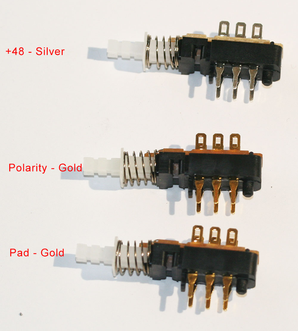
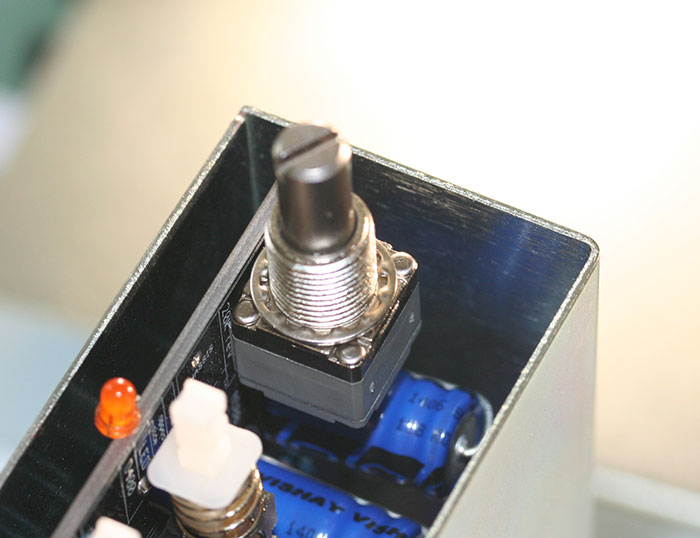
Simply press them into place and solder them so that they fit tight to the PCB.
If you like, you can pop the caps on now, the pad and phase switches get black caps, and the +48 switch gets the red cap. Wait, actually it's your pre do what you like!
Pots/Grayhill Switches
There are two options for controlling gain and output in the Elements series. The default output option when purchasing the kit is a potentiometer and the input is a Grayhill.
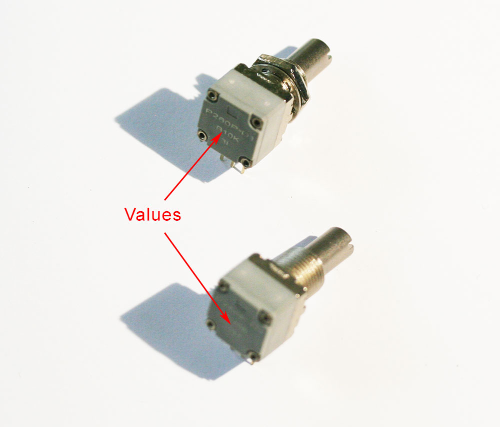
10K Lin (B10K) and 20K Rev Log (C20K) potentiometers shown. You can identify them by looking at the rear of the pot where their values are identified. Before inserting the pots, clip off the anti-rotation lug with your angle clippers. The lugs are not used here and prevent the faceplate from sitting flush.
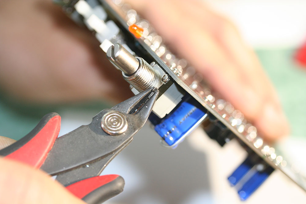
Cutting off the anti-rotation tab shown above. Soldering the pots in place is simple. Insert the pots so the shaft points out from the front of the PCB and sits tight to the PCB then solder them in place.
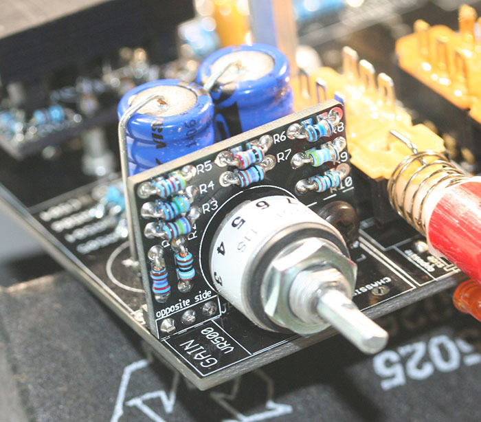
You may have opted for the Grayhill option for either the gain, output, or both. Some users prefer the Grayhill option for easier recall, stereo tracking, and a smaller gain rotation steps. The kit comes with a Grayhill, PCB, bracket, 3 pin header, 10 resistors, washer, and two screws. Older kits came with a shaft reducer to allow the 1/8" Grayhill shaft to fit in the 1/4" knob hole. We now ship the kits with a 1/8" shaft knob so the reducer is not required.
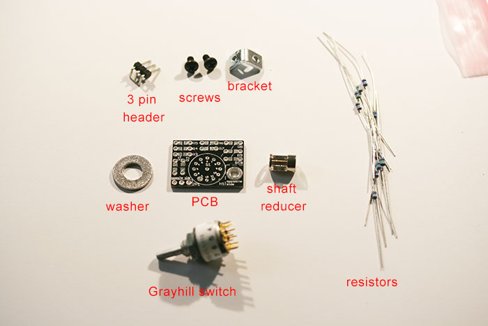
Grayhill gain kit is shown above. The 1/8 watt resistors can simply be bent near the body with your fingers and soldered into place. For the gain pot, the value placements are:
R1: 12.4Ω or 12.7KΩ
R2: 3.83Ω or 3.9KΩ
R3: 1.74KΩ
R4: 825Ω or 845Ω
R5: 402Ω/412Ω
R6: 237Ω
R7: 137Ω/140Ω
R8: 78.7Ω or 80.6Ω
R9: 49.9Ω
R10: 30Ω
For the output pot all of the positions get a 1KΩ pot.
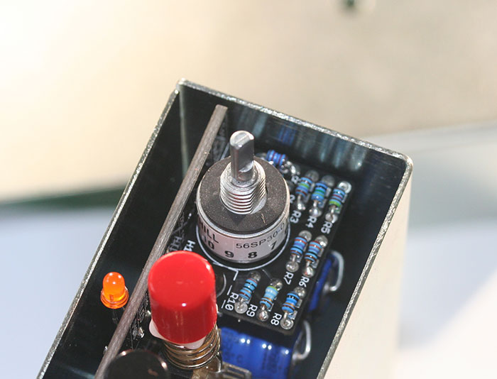
Next solder the 3 pin header in place on the rear of the PCB with the longer lead side. It is critical that the header sits flush and square to the PCB. Start by soldering one long header lead so you can adjust the positioning by reheating that lead. Once you are happy it is flush and square, solder the other two leads into place and trim the leads at the front of the PCB. Insert the switch by aligning pin 1 on the switch with pin 1 on the PCB.
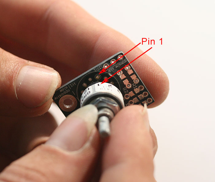
Make sure the switch is flush to the front of the PCB and solder it into place. Don't forget the middle pin!
Finally, look at the bracket and identify the short leg.
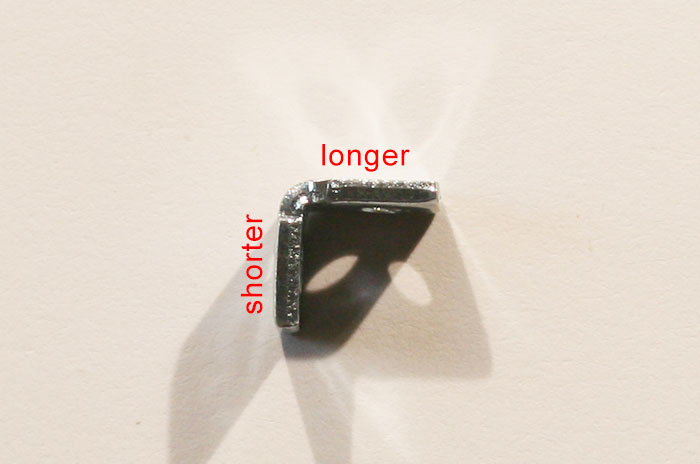
The short leg mounts to the Grayhill PCB using one of the 4-40 screws. Now place the Grayhill assembly on the PCB and mount the long side to the main PCB using the second screw 4-40 screw. If you have the bracket right, the Grayhill PCB will sit flush with the main PCB at a 90-degree angle. Simply solder the header into place.
Keep the shaft adaptor and washer in a safe place for now (like on the switch). You'll need them for the final assembly.
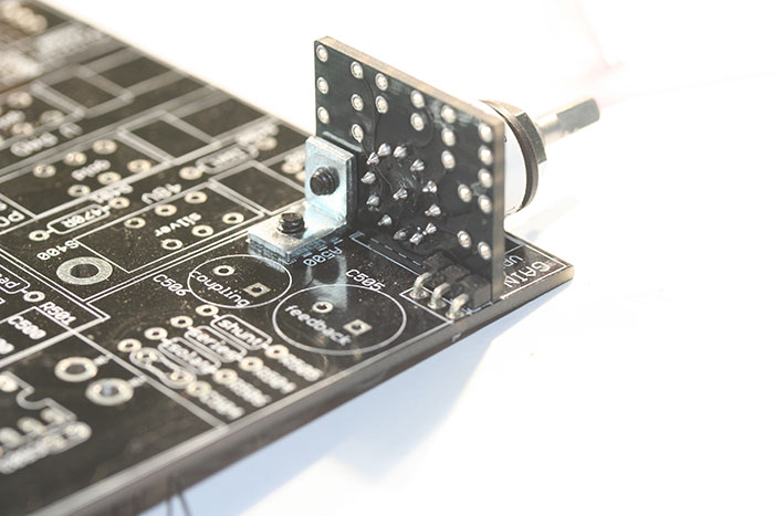
Here is a rear view of the assembly. Notice the PCB is flush and at 90 degrees.
DI Jack
The DI jack is a gold plated and is inserted flush to the PCB. Too easy!
Transformer
There are two styles of input transformer. The Gold and Bronze have PCB lead transformers and the Copper has an input transformer with wire leads. For the PCB pin transformers, align the pin 1 with the pin 1 on the PCB. Pin one on the transformers is identified with a dot.
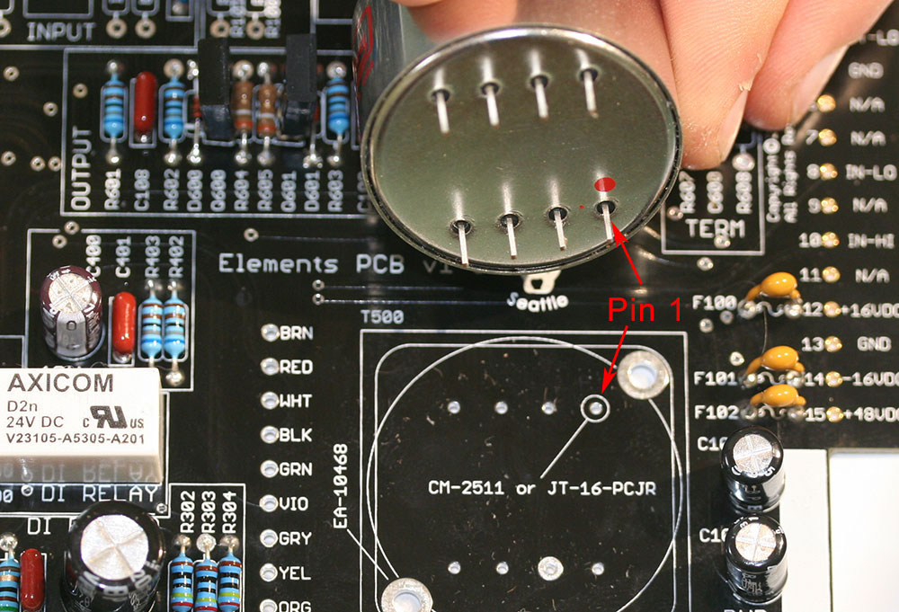
The Bronze input has the dot on the bottom and the Gold has it on top. Mount it flush to the PCB and solder it into place.
The wire lead Copper input is mounted using the two supplied #4-40 screws with the leads facing the input transformer pads.
Two #4-40 screws hold the copper transformer in place. Next, simply follow the pad/wire color coding to solder the wires into place. There are two green leads and two green pads, it does not matter which lead goes into which pad but they both need to be installed. Trim your wire leads shorter to eliminate the risk of noise.
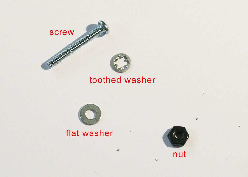
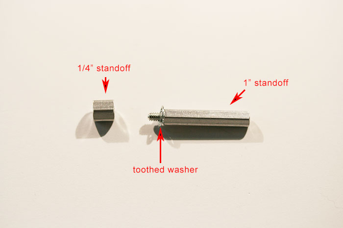
The output transformers all get installed similarly. Grab the two 1" #4-40 screws, #4 flat washers, toothed washers, and #4 nuts from the hardware kit.
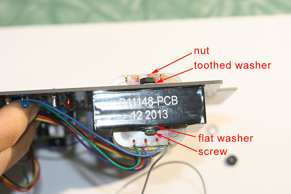
Place a flat washer on a screw and insert it into the top (wire side) on the transformer. Mount the transformer so the wires face the pads (for the bronze this is either way) and secure it in place with the lock washer and a nut at the bottom.
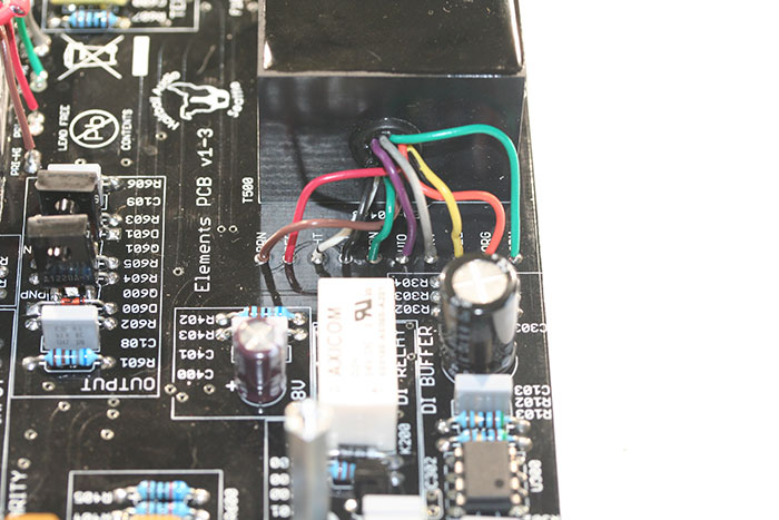
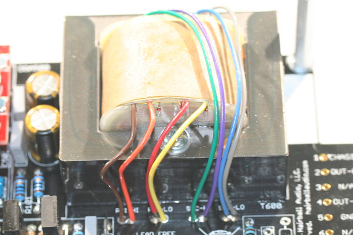
Now you can wire the output. You'll note there are four labels on the PCB, each with two pads. For Gold and Copper, we'll only be using one pad per label. For Bronze, you use both. It doesn't matter which pad you use at each label (they're shorted), but you must mount the correct color wire in the right label. Again you'll want to trim access lead before soldering.
Elements Output Transformer Wiring
| Label | Gold | Copper | Bronze |
| Pri-Hi | Brown | Brown | Brown and Orange |
| Pri-Lo | Red | Red | Red and Yellow |
| Sec-Hi | Orange | Green | Green and Purple |
| Sec-Lo | Yellow | Gray | Blue and Gray |
Copper will have a purple and blue lead remaining. You need to cut these short and solder them directly together. To avoid having this connection short to ground through the module enclosure, you should cover it with electrical tape or a small piece of shrink wrap.
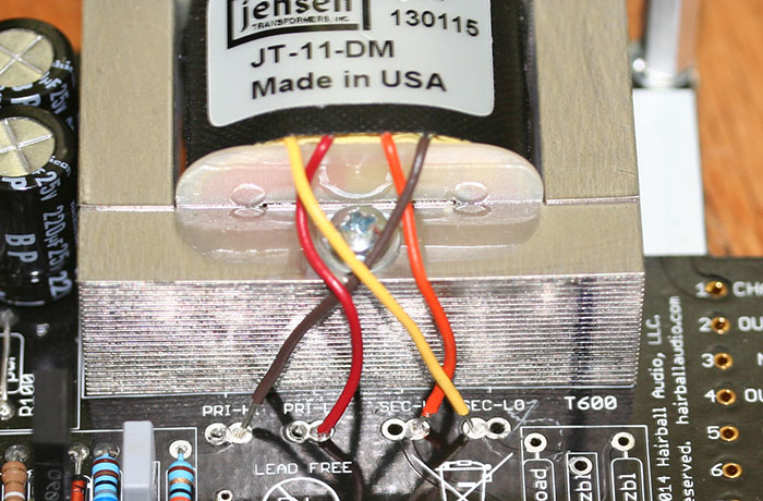
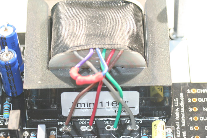
Here is what they look like installed:
Gold shown above.
Copper shown above.
.
Bronze shown above.
Installing the Op-Amp
Installing the op-amp is easy. Simply align it with the sockets and press it firmly into place. To avoid damage, grip it using the PCB sides rather than a component.
Final Assembly
Here is the fun part! It's the part where your module finally comes together.
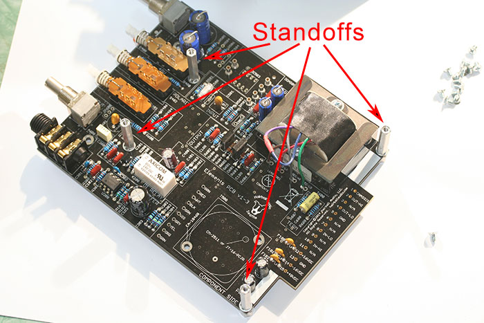
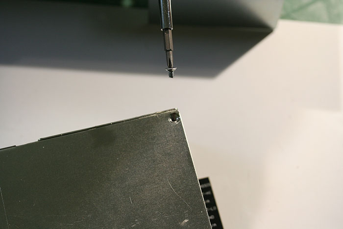
Start by grabbing four of each 1/4" standoffs, 1" standoffs, and toothed washers. Place a toothed washer over the male end of a 1" standoff and insert it into one of the 4 PCB moaning holes. Tread a 1/4" standoff onto this end through the bottom.
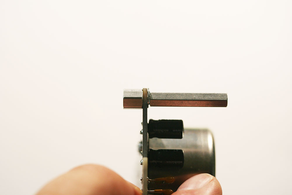
Toothed washer is on the top side of the PCB.
Now you can mount the enclosed panels using the remaining 3/16" #4-40 screws. The enclosure sides are identical. The orientation of the mounting holes will show you which way they are installed.
If you have potentiometer controls you'll need to clip off the anti-rotation lug with your clippers. You can also slide the tooth washer that came with the pot on to the shaft. It needs to sit behind the front panel.
For the pot, place the supplied toothed washer behind the faceplate.
For the Grayhill, you may or may not want to place the supplied rubber spacer behind the faceplate. See what makes the faceplate sit even and straight. Now slide the panel on and secure it in place with the DI nut. Note you may need to wiggle the LED into the LED hole. Again, it's a little sexy.
For the DI and pots, simply add the nut.
We are in the process of moving from 1/4" to 1/8" gain and output holes. If you have the Grayhill option and you have 1/4" holes, you'll need to add the supplied washer to the front and secure it with the Grayhill nut. Discard the toothed washer.
Use your eye for alignment. You'll need to play with it a little to make sure the Grayhill switch and washer is centered.
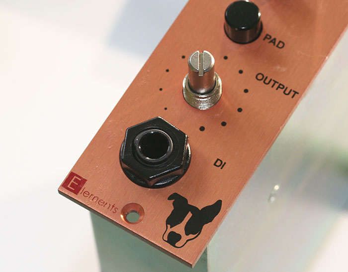
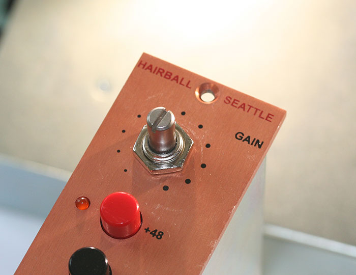
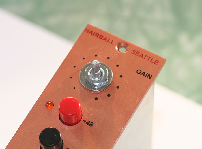
Last, add the knobs. For the pots this is simple. Set the pot shafts to full CCW and align the knobs to the first dot. Tighten both set screws with a 1/16 hex key.
If you have an older kit with the shaft reducer, the Grayhill is slightly more complicated. This video will walk you through the process. It's not really all that difficult.
You're done!