Now that you've assembled all of the PCBs, we can put it all together. If you purchased the active link add-on, you should jump to the active link build guide and assemble that PCB before completing this next step.
Note: Much of the screw hardware in this tutorial is black. The screws in your kit will be mostly silver.
With the front panel removed, re-attach the main PCB to the rear and sides panel. You need to tilt the PCB slightly to ensure the output XLR release tab feeds through the output XLR hole. Confirm the XLR flanges are fed through the holes and sit flush to the rear side of the back panel. You may have to adjust the RCA connector a little so it sits aligned in its hole.
Start by securing the L brackets to the rear panel with the silver #4 short silver pan head screws.
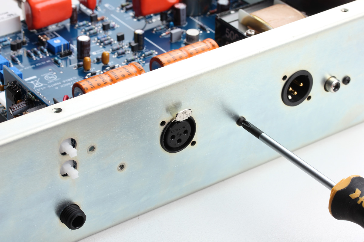
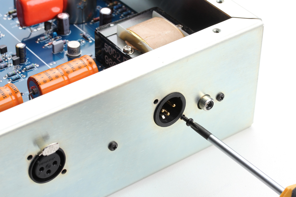
Next, you can secure the XLR connectors using the supplied silver Plastite screws.
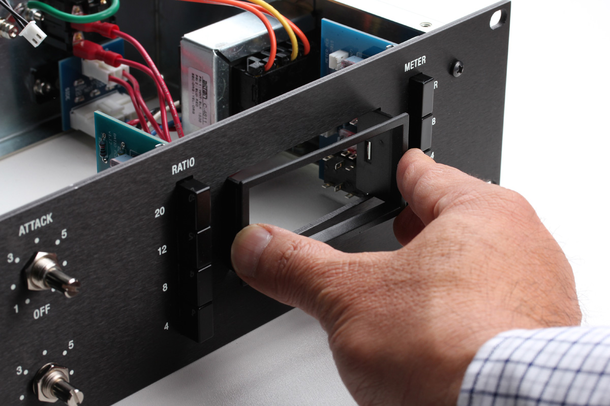
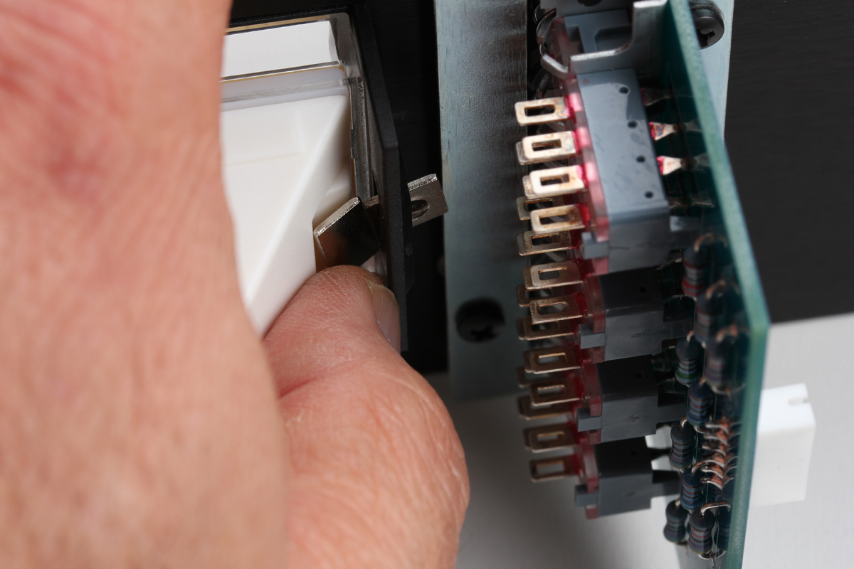
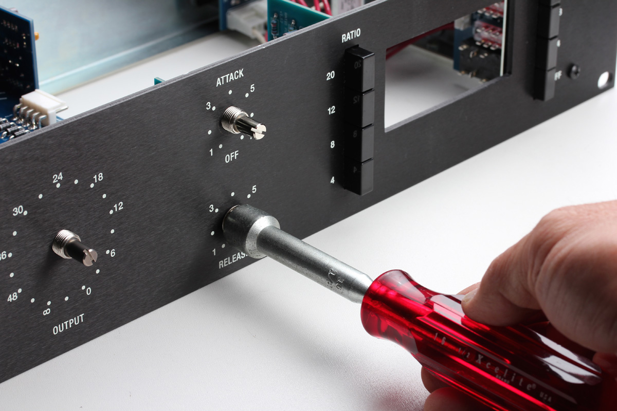
Now install the ratio PCB assembly just like you did the meter assembly at the beginning of the guide. Just like the meter PCB, there may be some small adjustments to ensure the push switches centered and square in the opening.

Next, open the VU meter box and remove the bezel. Be careful not to misplace the small back of mounting hardware. Slide the bezel through the front opening until it sits flush with the panel.
On the rear of the front panel adjust the meter so it sits in the opening centered in the bezel and install a mounting tab as shown on either side.
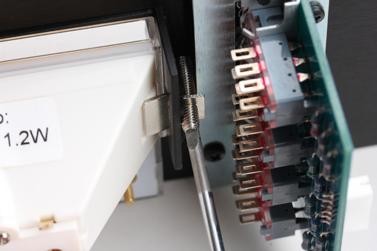
Now insert the retaining screws with the slotted end facing you and tighten each using a slotted screwdriver. DO NOT OVERTIGHTEN THESE SCREWS! If these screws are tightened too far, the meter card will bow and interfere with the needle movement. Tighten them just enough to secure the meter.
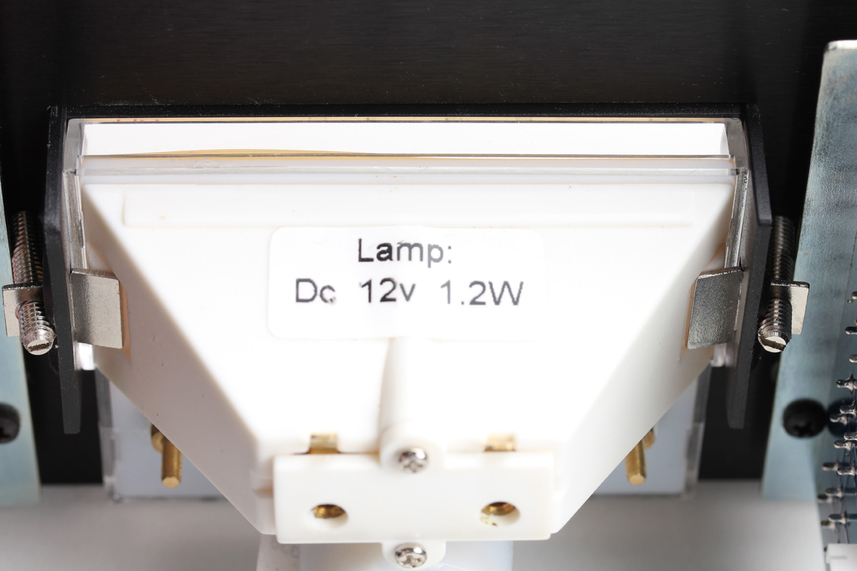
A perfectly secured meter.
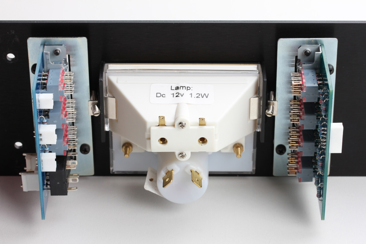
The complete switch and meter assembly should resemble the image below.
Next, attach the attack and release network, then carefully slide the panel over the main PCB front panel control pots. Remove the washers and nuts from the pots. You'll need to line up all four of the pots to get the panel installed. Give extra attention to the release pot as it can be pulled back from its leads. You can push them back into the tabs on the bottom of the pot, however, after a few times, the leads may break.
Once you've successfully attached the front panel, you can secure it with the supplied #6 pan screws you used earlier in the power supply section. The anti-rotation tab for each pot will not rest into a milled hole in the rear of the front panel until the pot nuts are installed.

Place a washer then nut over each pot and slowly tighten each nut a little bit at a time with your nut driver, confirming the anti-rotation tabs enter the milled holes. Do not overtighten these, you're not putting a wing on an airplane. Go easy.
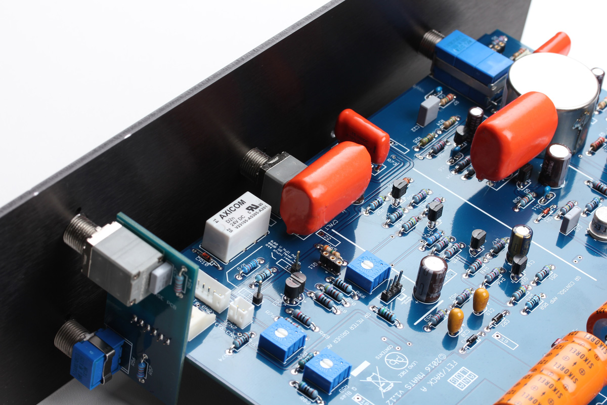
Now with the build assembled we can add the final wiring. All of the connectors need to be inserted in the proper direction. Luckily, the connectors are keyed to only allow them to be inserted in one direction. Start with the 6 pin PH (small) connector. Attaching one end to CN3 on the main PCB and the other to CN2 on the ratio PCB.
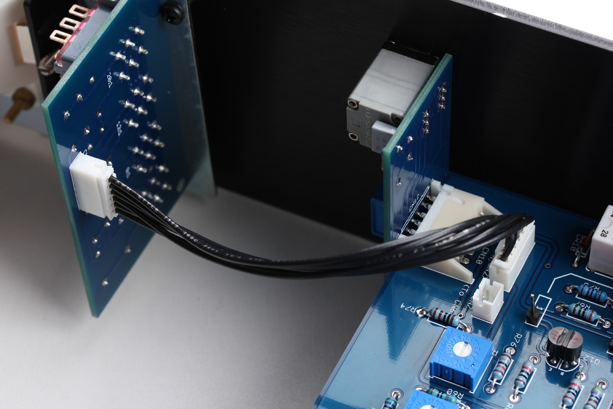
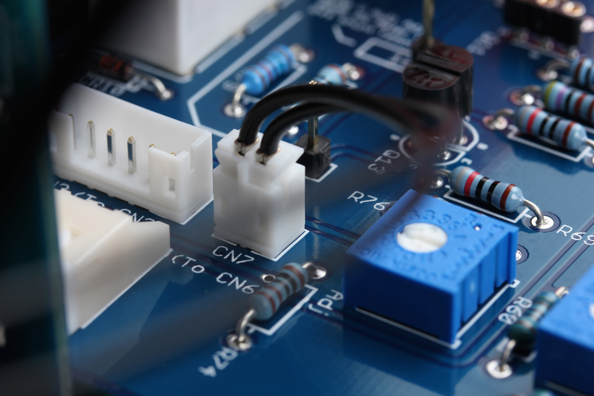
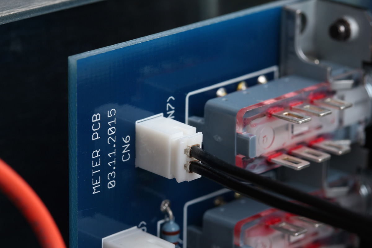
Next, grab the 2 pin PH connector and connect one end to CN7 on the main PCB and the other to CN6 on the meter PCB.
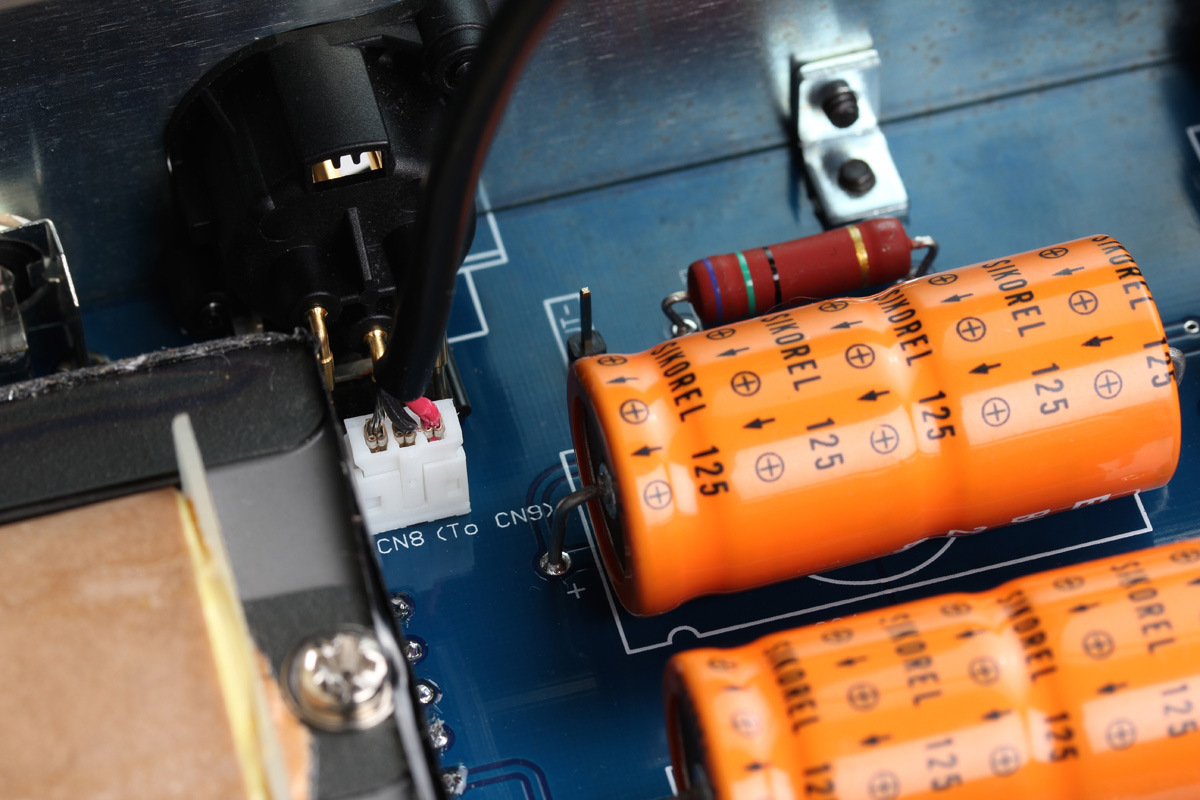
Finally, locate the 3 pin shielded PH cable and connect one end to CN8 by the output XLR and the other end to CN9 on the meter PCB.
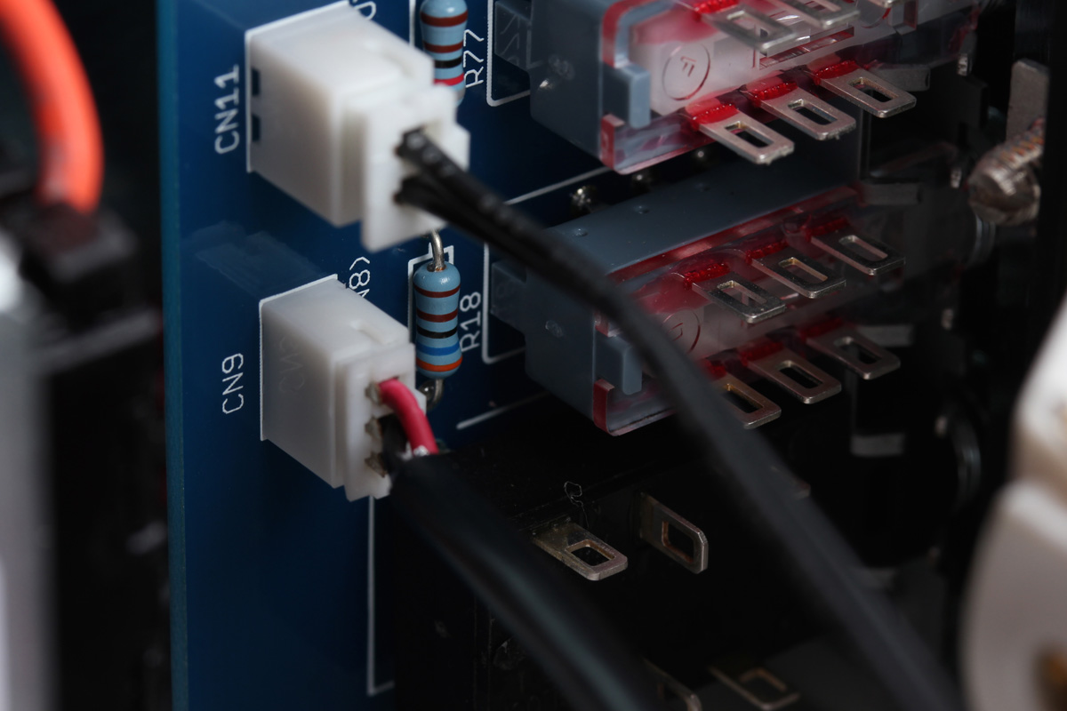
CN11 on the meter PCB is a 2 pin XH (medium) connector that has 6.3mm quick disconnects on the other end. Connect header to CN11, then connect the quick disconnects to the lower larger signal terminals on the VU meter. There is a white lead and a black lead; it does not matter which quick disconnect attaches to which terminal. Press them on so they slide all the way down.
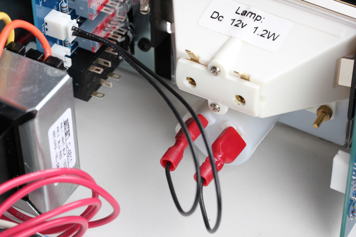
If you have not yet done so, assemble the VU lamp circuit board. Solder the connector CN15 and large 240Ω resistor. Your resistor may not be a white block as pictured. It is most likely a traditional looking large film resistor and it will hover off the PCB a little to help dissipate heat. The last step is to solder the PCB to the small lamp terminals. This PCB may have to be removed to replace the lamp, so "tack solder" it in place with just enough of a joint to secure it to the terminals. Once it's secure you can connect that XH header that shares the power transformer secondary to CN15.

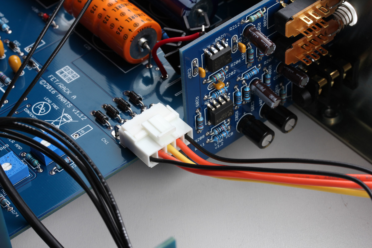
Lastly, connect the power transformer secondary connector to CN1 on the main PCB.
Last step - put the knobs on. Before we start though, a few words about the panel legends vs. the knob position. Historically, the angle of rotation of older t-pads and potentiometers has differed from modern parts. Even modern pots have different angles of rotation between manufacturers. So don’t expect the knobs to line up perfectly with the markings on the front panel. We’ll line them up according to this guide for calibration purposes. This will give everyone a standard from which to work from. Feel free to change your knob’s mounting angle to suit your own working habits once calibration is completed.
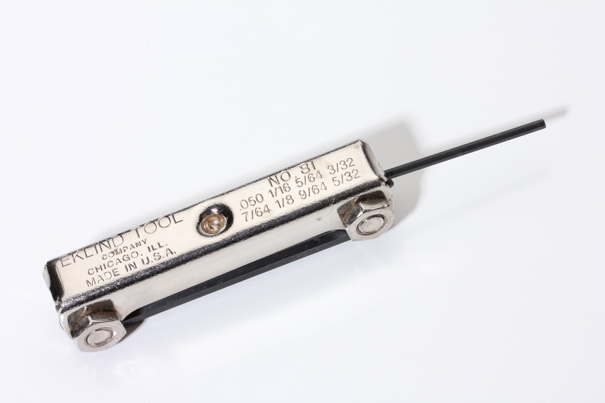
Start with getting the proper tools. You’ll need two imperial Allen keys. Don’t try to use metric keys or you’ll risk rounding out the grub screws, rendering your knobs useless (or at least stuck). You’ll need one in 0.05" inch and one in 5/64 inch.
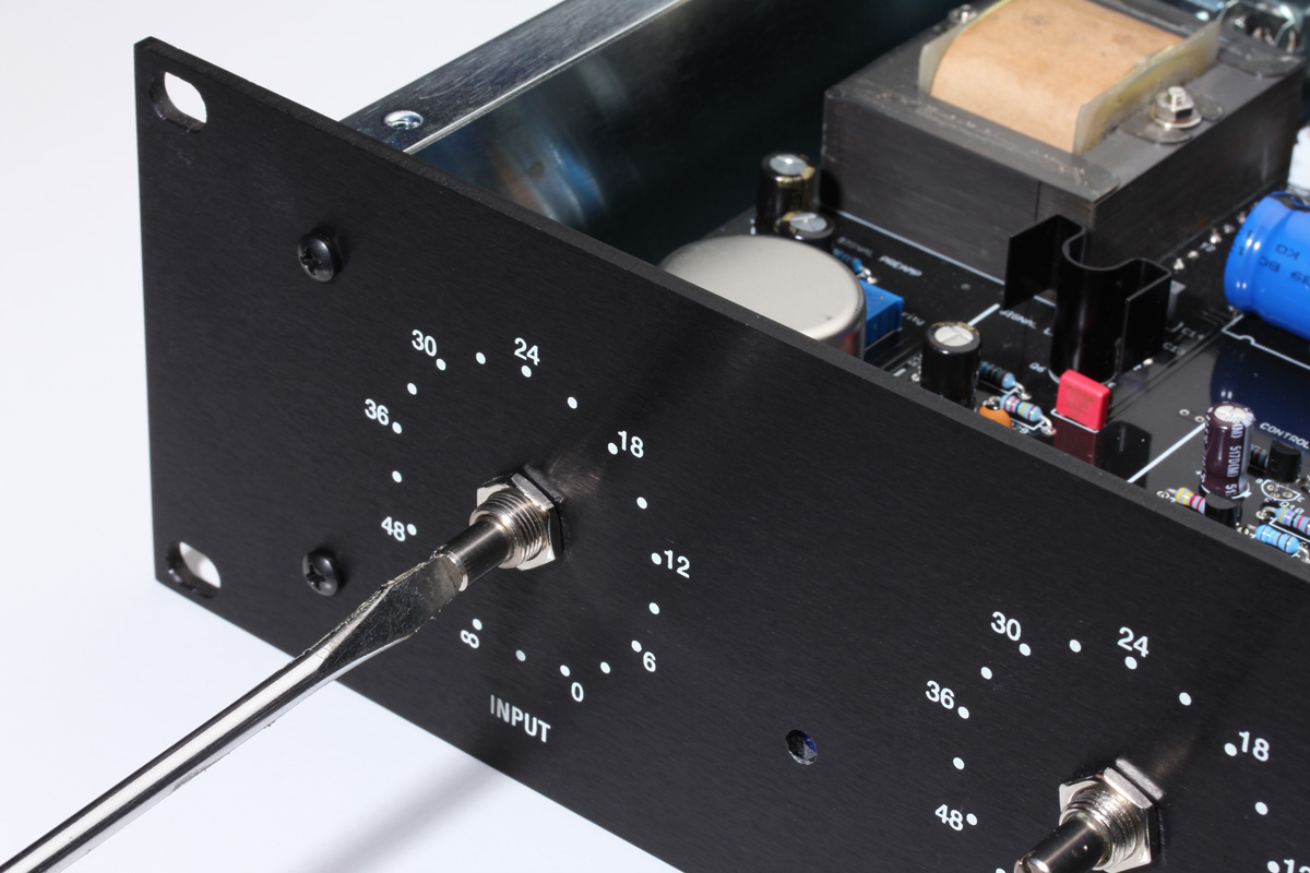
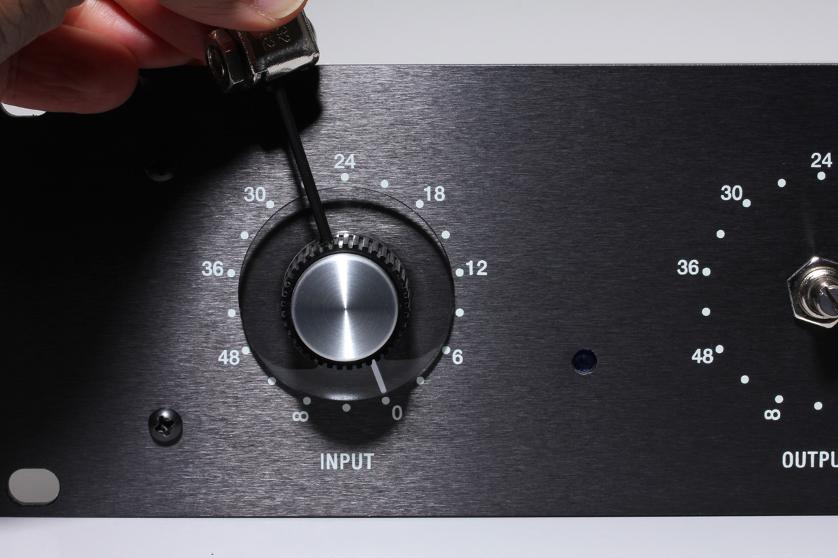
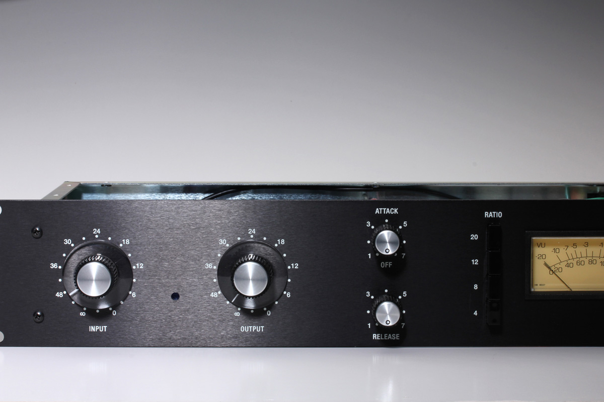
Turn both the Input and Output potentiometer shafts fully clockwise - that means all the way up to 11 (actually on the FET/RACK this is all the way to zero). Now, without disturbing the position of the shaft put the larger knob on and align the pointer with “0” on the front panel. Tighten one screw until it holds then turn the knob in a way that makes it easy to tighten the second screw. Repeat with the other level control.
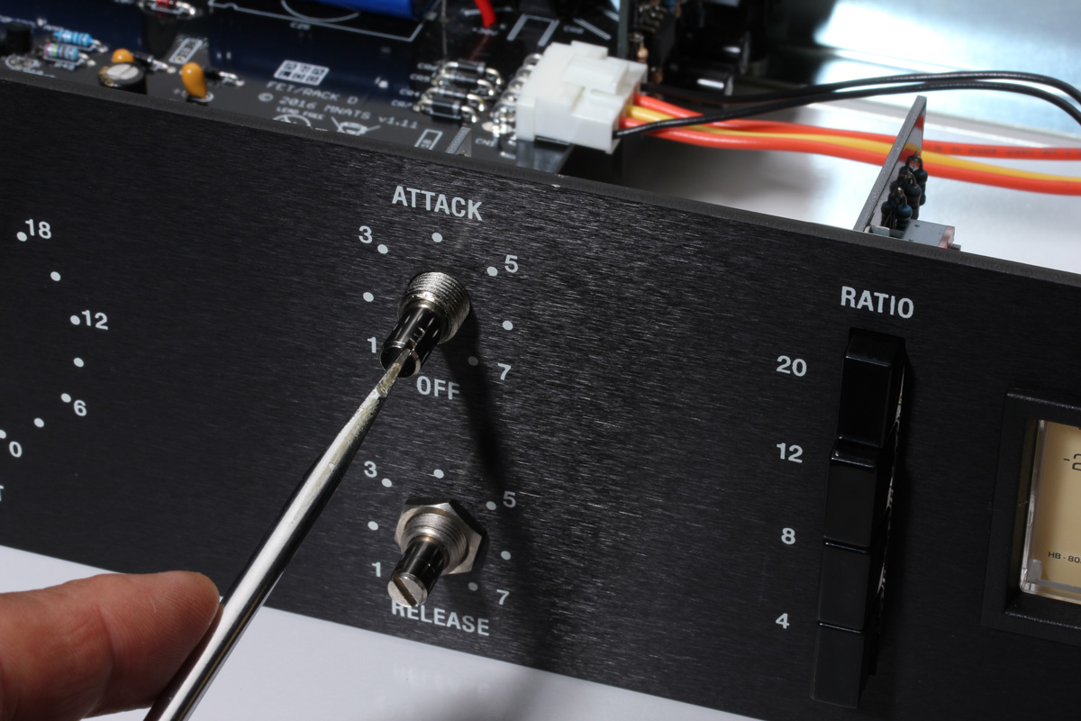
Next, turn both the Attack and Release shafts fully counter-clockwise (opposite to the way we turned the other controls above). Take the smaller knob, put it over the attack control and align the circle on the knob with the “OFF” legend on the front panel. Tighten one screw, then the other.
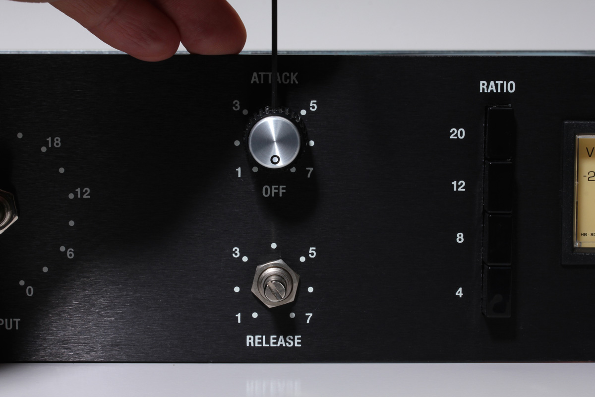
For consistency let’s attach the release knob with the same orientation - all the way to the 6 o’clock position. Note that when the Input and Output knobs are rotated counter-clockwise they may not match each other’s position.
This is normal due to the differences between the t-pad and potentiometer.
Your FET/RACK build should now be fully assembled. For safety, you can install the bottom panel using the supplied #6 flat head screws. You'll need to leave to top off for the next step, calibration!